Difference between revisions of "AY Honors/Automobile Mechanics/Answer Key"
| Line 92: | Line 92: | ||
===d. Difference between drum brakes and disk brakes, standard brakes and power brakes, and the parking brake=== | ===d. Difference between drum brakes and disk brakes, standard brakes and power brakes, and the parking brake=== | ||
| + | [[Image:Drum Brake parts.jpg|thumb|400px|Drum Brakes]] | ||
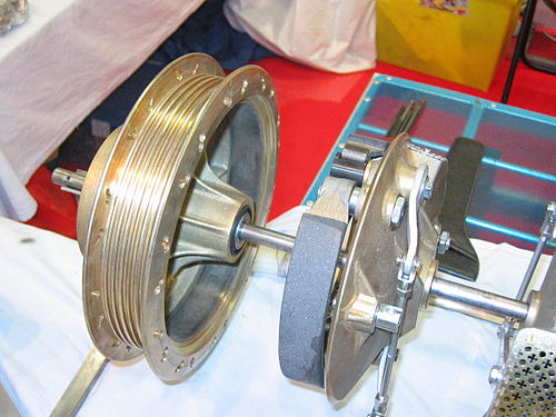
| + | The diagram on the right shows the parts of a '''drum brake''' system. The brake is taken apart in this photo showing the brake drum on the left, and the brake shoes on the right. In operation, the shoes fit inside the drum. The drum rotates with the wheel, and the shoes are held stationary. When the brakes are applied, the shoes press against the inside surface of the drum, and the friction produced slows the wheels, stopping them ultimately. | ||
| + | <br style="clear:both"/> | ||
| + | [[Image:Disk brake dsc03680.jpg|thumb|400px|Disc Brakes]] | ||
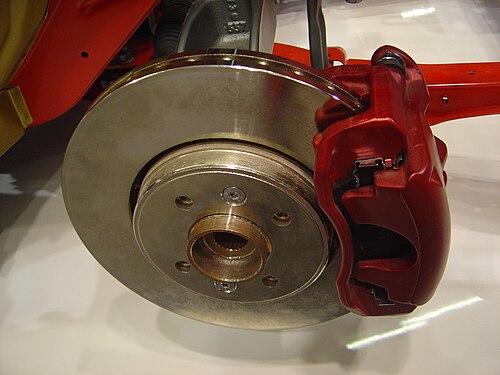
| + | The diagram on the right shows the parts of a '''disk brake''' system. Here, the disk (gold) rotates with the wheel, and a stationary pair of ''calipers'' (red) squeeze both sides of the disc. | ||
| + | <br style="clear:both"/> | ||
| + | In '''standard brakes''' the energy supplied by the operator’s foot in pushing down on the brake pedal is transferred to the brake mechanism on the wheels by various means. A mechanical hookup has been used since the earliest motor vehicles, but hydraulic pressure is used most extensively at the present time. Mechanically operated braking systems are obsolete on today’s automobiles, but these systems may be used for a portion of the braking systems in many vehicles. | ||
| + | |||
| + | '''Power braking systems are designed to reduce the effort required to depress the brake pedal when stopping or holding a vehicle stationary. Most power brake systems use the difference in pressure between intake manifold vacuum and atmospheric pressure to develop the additional force required to decrease brake pedal pressure. When a vehicle is powered by a diesel engine, the absence of intake manifold vacuum requires the use of an auxiliary vacuum pump. This type of pump usually is driven by the engine or by an electric motor. | ||
| + | |||
| + | The '''parking brake''' usually is operated by an auxiliary foot pedal or hand lever located in the driver compartment. This brake mechanism is designed to keep the vehicle stationary when the operator is not present. It is usually integrated into the disk or drum brake system (which ever is used) and locks in place until released by the operator. | ||
==4. Perform typical automotive maintenance as listed below:== | ==4. Perform typical automotive maintenance as listed below:== | ||
Revision as of 01:52, 8 August 2006
1. Properly start an automobile or light truck engine with an automatic transmission and one with a standard transmission. Explain why it is necessary for the engine to have the proper oil, water, fuel, and battery pressures and levels for proper engine operation.
Starting an Automatic
To start a vehicle with an automatic transmission, sit in the driver's seat and make sure the vehicle is in Park. Insert the key in the ignition and turn it clockwise as far as it will go. The engine should crank. Do not depress the gas pedal. As soon as the engine starts, release the key. To turn it off, turn the key counter-clockwise.
Starting a Manual
To start a vehicle with a manual transmission, sit in the driver's seat and push the clutch pedal all the way in with the left foot. The clutch pedal is the third one from the right, and this is often the one farthest to the left (although some vehicles have the parking brake to the left of the clutch).
Make sure the parking brake has been applied. Inexperienced drivers should also shift the vehicle into neutral so that if the foot slips off the clutch after the engine starts, the car does not move. Even with the vehicle in neutral, it is still important to depress the clutch, as many autos have a switch in the clutch which prevents the engine from starting unless the clutch is depressed. Insert the key in the ignition and turn it clockwise as far as it will go. The engine should crank. Do not depress the gas pedal, but leave the clutch pedal depressed. As soon as the engine starts, release the key. To turn it off, turn the key counter-clockwise.
Importance of Proper Pressures and Levels
Oil keeps the engine lubricated and reduces friction between the moving parts of the engine. Friction causes heat, so if there is insufficient oil pressure in the engine, it will quickly overheat. Running an engine without oil for any amount of time will damage it, and doing so for an extended period will destroy it.
Water circulates through the engine to cool it. Running an engine too hot will dmage it.
Fuel is what makes the engine go. If the vehicle has insufficient fuel pressure, the fuel will not flow into the combustion chamber at the proper rate.
The Battery provides energy to run the engine's starter. If the battery's voltage level is low, it may not be able to turn the starter.
2. Explain the principles of four- and two-cycle engines and the difference between gasoline and diesel engines. Explain the major differences between carburetor fuel systems and fuel-injection systems.
Four-cycle Engine
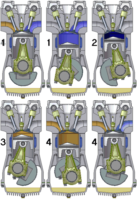
A four-cycle engine is so named because it makes four strokes to generate power. These strokes are as follows:
- Intake Stroke: During this stroke, the piston draws a mixture of fuel and air into the cylinder. The fuel and air enters through an intake valve which opens during this stroke.
- Compression Stroke: Once the fuel and air have been drawn into the cylinder, the intake valve close and the piston returns towards the engine's head. This compresses the fuel.
- Power Stroke: When the piston reaches the top of the cylinder, the spark plug fires, igniting the compressed fuel and air mixture and causing an explosion. This explosion causes the gases to expand which powers the piston downwards again. This is where the engines power (and noise!) comes from.
- Exhaust Stroke: When the piston reaches the bottom of the cylinder, the exhaust valve opens, and as the piston returns to the top of the cylinder again, the exhaust gases are pushed out. When the clylinder reaches the top again, the four cycles are ready to repeat.
Two-cycle Engine
This link has an animation of a two-cycle engine in action. (We need to come up with our own animation here that can be freely distributed).
Power and Exhaust Stroke: In a two-cycle engine, the spark plug fires every time the piston reaches the top of the cylinder. This is the beginning of the power and exhaust cycle. As in the four cycle engine, the spark plug firing causes a compressed air/fuel mixture in the cylinder to explode, and the expanding gases drive the piston downward. As the cylinder goes down, it compresses another air/fuel mixture inside the crankcase - not inside the cylinder as in the four-stroke engine. The crankcase is the area beneath the piston, and the cylinder is the area above the piston. When the piston nears the bottom of this stroke, it uncovers an exhaust outlet and it also uncovers a passage between the crankcase and the cylinder. The compressed air-fuel mixture in the crankcase then rushes through this passage-way into the cylinder, forcing the exhaust gases out of the cylinder though the exhaust outlet. Some of the air/fuel mixture is also forced out the exhaust outlet, and this unfortunately decreases the engine's fuel efficiency and increases its pollution output. The piston's head is shaped in such a way as to minimize this waste, but it does not entirely eliminate it.
Intake and Compression Stroke: After the piston reaches the bottom of the stroke, it begins travelling upwards again, compressing the air/fuel mixture that rushed into the cylinder from the crankcase during the previous stroke, and simulataneously drawing more air and fuel into the crankcase. By the time the piston reaches the top of the cylinder, the air/fuel mixture is very highly compressed - much more compressed than it was in the crankcase. It is at this point in the cycle that the intake valve closes and the spark plug fires.
Because the crankcase is opened to the cylinder during its operation, oil in the crankcase makes its way into the cylinder where it is compressed and combusted along with the fuel. If this situation were ignored, the engine would soon burn up all its oil, leaving itself unlubricated. The engine would soon get so hot that its parts would fuse together and destroy itself. This is addressed by adding oil to the fuel (often one part oil to sixteen parts fuel). Thus the engine's oil supply is refreshed on every stroke of the piston. This unfortunately increases the pollution levels generated by two-stroke engines.
Gasoline verses Diesel Engines
In many respects, the four-stroke gasoline engine and the four-stroke diesel engine are very similar. They both follow an operating cycle that consists of intake, compression, power, and exhaust strokes. They also share in the same system for intake and exhaust valves. The fuel and air mixture is ignited by the heat generated by the compression stroke in a diesel engine versus the use of a spark ignition system on a gasoline engine. The diesel engine needs no ignition system. For this reason, the gasoline engine is referred to as a spark ignition engine and a diesel engine is referred to as a compression ignition engine.
The fuel and air mixture is compressed to about one-twentieth of its original volume in a diesel engine. In contrast, the fuel and air mixture in a gasoline engine is compressed to about one-eighth of its original volume. The diesel engine must compress the mixture this tightly to generate enough heat to ignite the fuel and air mixture.
The gasoline engine mixes the fuel and air before it reaches the combustion chamber. A diesel engine takes in only air through the intake port. Fuel is put into the combustion chamber directly through an injection system. The air and fuel then mix in the combustion chamber.
The engine speed and the power output of a diesel engine are controlled by the quantity of fuel admitted to the combustion chamber. The amount of air is constant. This contrasts with the gasoline engine where the speed and power output are regulated by limiting the air entering the engine.
Carburator verses Fuel Injection Systems
The carburetor serves the following basic functions:
- The carburetor mixes fuel and air Into the correct proportions for the most efficient use by the engine. The carburetor also must constantly vary the mixture proportions to meet the engine’s needs as Its speed and load requirements vary.
- The carburetor regulates engine speed and power output.
- The carburetor atomizes the fuel as it mixes it with the air.
Fuel injection systems are an increasingly popular alternative to the carburetor for providing an air-fuel mixture. They inject, under pressure, a measured amount of fuel into the Intake air, usually at a point near the intake valve. Fuel injection systems provide the following advantages.
- Fuel delivery can be measured with extreme accuracy, giving the potential for improved fuel economy and performance.
- Because the fuel is injected at the intake port of each cylinder, fuel distribution will be much better and fuel condensing in the manifold will not be a problem.
- The fuel injector, working under pressure, can atomize the fuel much finer than the carburetor, resulting in improved fuel vaporization.
3. Describe the construction of a typical gasoline engine and explain briefly the function of these units:
a. Engine: crankshaft, connecting rods, pistons, camshaft, valves, oil pump, carburetor, fuel injectors, ignition distributor, fuel distributor, electrical system including alternator, battery, and regulator
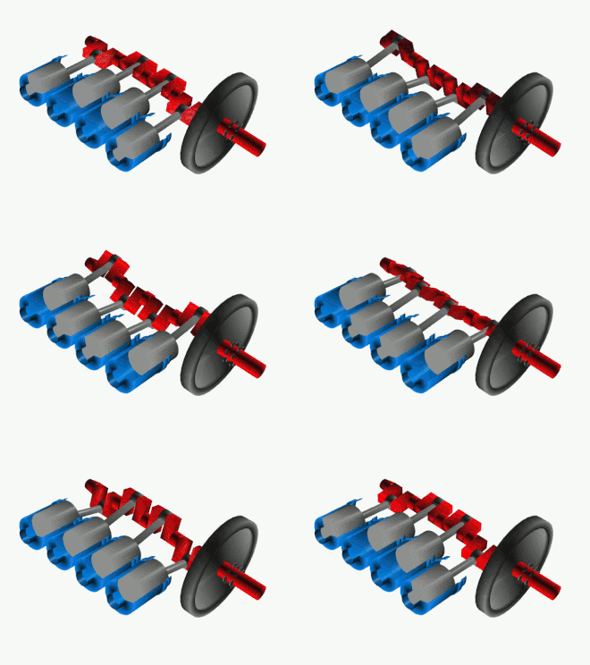
As can be seen in the diagram to the right, the pistons drive the crankshaft via the connecting rods. The connecting rods and crankshaft convert the back-and-forth motion of the pistons into rotary motion.
The camshaft is a smaller rotating shaft with small "bumps" on it called cams. As the cams rotate, they lift and lower the valves at just the right time to allow gasses to either flow into the cylinder or escape from it.
The oil pump moves oil through the engine to keep the internal parts well lubricated.
The function of the carburetor and fuel injector were covered in requirement 3.
The ignition distributor has several jobs to do in the ignition system. First, it must close and open the primary circuit to produce the magnetic buildup and collapse in the ignition coil. Second, it times these actions so the resultant high-voltage surges from the secondary will be produced at the right time. Third, it must establish a timing sequence to direct the high-voltage surges to the proper spark plugs.
The distributor injection system used in automotive diesel engines is classed as a low-pressure system in that pumping, metering, and distribution operations take place at low pressure. The high pressure required for injection is built up by the injector at each cylinder. A suction pump lifts fuel from the tank and delivers it to the float chamber. From here a second low-pressure pump delivers the fuel to the fuel distributor. Fuel passes through the distributor to the metering pump, where it is divided into measured charges. The fuel charges then are delivered back to the distributor, where they are sent to the injectors in the proper sequence.
Electrical system
The alternator is an electrical generator. As the engine turns a shaft in the alternator, it generates electricity to run everything in the car's electrical system, including the headlights, onboard computers, radio, and more. It also recharges the battery.
The battery is used primarily for starting the vehicle. When the car is not running, the alternator cannot generate any electricity, so the battery must do this. It will also power the headlights, radio, and a few other things. The most common way a battery "dies" is when someone leaves the headlights on for too long with the engine off.
The regulator evens out the voltage coming out of the alternator before it is fed to the rest of the electrical system. The voltage from the alternator can vary depending on a lot of different factors, and it is the regulator's job to make sure that none of the other components have to deal with varying amounts of power. Without the regulator, the headlights would brighten and dim as the alternator's voltage varied.
b. Difference between standard transmission and automatic transmission and how the engine torque is transmitted to both kinds of transmissions; the purpose of overdrive
The transmission couples the engine to the drive shaft and has to main functions:
- Control direction of travel (forward or revers)
- Provide the operator with a selection of gear ratios between engine and wheels so that the vehicle can operate at best efficiency under a variety of driving conditions and loads.
In a vehicle with a standard transmission the driver selects the desired gear manually. Torque is transferred between the engine and the wheels through a series of gears. In a vehicle with an automatic tranmission the transmission makes the gear selection itself depending on throttle position, vehicle speed, and the position of the shift control lever. Automatic transmissions are built in models that have two, three, or four forward speeds and in some that are equipped with overdrive. Operator control is limited to the selection of the gear range by moving a control lever.
TODO describe torque in an automatic.
c. Difference between rear wheel drive and front wheel drive
If you put a car on a hydraulic lift, raised all four wheels off the ground, turned on the engine, and put it in gear, the rear wheels of rear-wheel drive vehicle would turn, while the front wheels of a front-wheel drive vehicle would turn. In a four-wheel drive vehicle, all four wheels would spin. The terms simply indicate which wheels are connected to the engine via the transmission.
d. Difference between drum brakes and disk brakes, standard brakes and power brakes, and the parking brake
The diagram on the right shows the parts of a drum brake system. The brake is taken apart in this photo showing the brake drum on the left, and the brake shoes on the right. In operation, the shoes fit inside the drum. The drum rotates with the wheel, and the shoes are held stationary. When the brakes are applied, the shoes press against the inside surface of the drum, and the friction produced slows the wheels, stopping them ultimately.
The diagram on the right shows the parts of a disk brake system. Here, the disk (gold) rotates with the wheel, and a stationary pair of calipers (red) squeeze both sides of the disc.
In standard brakes the energy supplied by the operator’s foot in pushing down on the brake pedal is transferred to the brake mechanism on the wheels by various means. A mechanical hookup has been used since the earliest motor vehicles, but hydraulic pressure is used most extensively at the present time. Mechanically operated braking systems are obsolete on today’s automobiles, but these systems may be used for a portion of the braking systems in many vehicles.
Power braking systems are designed to reduce the effort required to depress the brake pedal when stopping or holding a vehicle stationary. Most power brake systems use the difference in pressure between intake manifold vacuum and atmospheric pressure to develop the additional force required to decrease brake pedal pressure. When a vehicle is powered by a diesel engine, the absence of intake manifold vacuum requires the use of an auxiliary vacuum pump. This type of pump usually is driven by the engine or by an electric motor.
The parking brake usually is operated by an auxiliary foot pedal or hand lever located in the driver compartment. This brake mechanism is designed to keep the vehicle stationary when the operator is not present. It is usually integrated into the disk or drum brake system (which ever is used) and locks in place until released by the operator.
4. Perform typical automotive maintenance as listed below:
a. Check engine and transmission oil levels.
b. Check water/anti-freeze level. Change and flush the cooling system.
c. Change engine oil and filter.
d. Change a tire/wheel assembly, following proper safety procedure.
- Locate the point on the car designed to take the jack. This is usually illustrated in the owner's manual, and is often a point on the chassis a few inches behind the front tire, or a few inches in front of the rear tire.
- Place chocks around two of the car's tires. If changing a front tire, place the chocks on the two rear tires. If changing a rear tire, place them on the front tires. Chocks are brick-sized blocks that prevent the car from rolling. Indeed, you can use about anything for a chock, so long as it will stand up to the pressure of a car being parked on it, and if it is tall enough to prevent the car from rolling over it. Bricks, blocks, blocks of wood, or even large rocks can be used as chocks, or you can use store-bought ones.
- Set the parking brake.
- Loosen the lug nuts, but do not remove them yet. It is easier to loosen them before jacking up the vehicle because the tires will remain stationary. Once the vehicle is jacked up, the wheels will easily rotate, making it more difficult to loosen the lug nuts. It may be necessary to remove the hubcap to get at the lug nuts. The hubcap usually prys off with a screw driver or with the end of the jack handle. Be careful not to damage the hubcap.
- Place the jack beneath the jack point and use it to lift the vehicle. Do not ever lift more than one tire from the ground at a time! This is a very dangerous thing to do, because it makes it very easy to knock a car off the jacks.
- Stop lifting the vehicle as soon as the tire is lifted from the ground.
- Finish removing the lug nuts.
- Once all the lug nuts have been removed, you may pull the tire/wheel assembly towards yourself and off the wheel mount. Once it's off, you can carefully roll it out of the way and get the new tire (or the same tire since this is likely an excercise, and there is likely nothing wrong with the tire in the first place).
- Lift the new tire onto the wheelmount, aligning the holes in the wheel with the bolts on the wheel mount. Push the tire into position and quickly put a lug nut or two in place. Get them all on, and finger-tight first, and then get the lug wrench out and begin tightening the first lugnut.
- After the first lug nut is tightened, move to the one on the opposite side of the wheel (or as near to opposite as you can get) and tighten it. Continue tightening the other nuts, going to opposite sides of the wheel each time so that they are tightend evenly. When they are all right, lower the jack.
- Remove the jack.
- Go around the lug nuts again, tightening them further. With the car's weight preventing the tires from rotating, you should be able to tighten them a little more (but don't overdo it).
- Congratulate yourself on a job well done.
e. Lubricate the chassis according to the vehicle service manual.
5. How often should the engine oil, transmission oil, and cooling fluid be changed?
6. Give some pointers on proper care of the vehicle and its finish, both interior and exterior.
References
Some of the material for this answer book was taken verbatim from Principles Of Automotive Vehicles, U.S. Army Manual Tm-9-8000. As an original work of the U.S. Federal Goverment, this document is in the public domain, so it is perfectly legal and ethical to include portions of it here.


