Difference between revisions of "AY Honors/Electricity/Answer Key"
m (- Category of AYHAB) |
|||
| (66 intermediate revisions by 6 users not shown) | |||
| Line 1: | Line 1: | ||
| − | = | + | {{HonorSubpage}} |
| − | == Explain and illustrate an experiment by which the laws of electrical attraction and repulsion are shown. | + | <!--{{Honor Master|honor={{#titleparts:{{PAGENAME}}|1|3}}|master=Technician}}--> |
| + | <section begin="Body" /> | ||
| + | {{ansreq|page={{#titleparts:{{PAGENAME}}|2|1}}|num=1}} | ||
| + | <noinclude><translate><!--T:47--> | ||
| + | </noinclude> | ||
| + | <!-- 1. Explain and illustrate an experiment by which the laws of electrical attraction and repulsion are shown. --> | ||
| + | This simple experiment can be performed with nothing more exotic than a roll of plastic, transparent tape - the kind usually found on a desk. Remove two 12" strips of tape from the roll and hold them by the end, one in each hand. Removing the tape from the roll will charge the strips with static electricity. | ||
| − | + | <!--T:3--> | |
| + | Now bring the two strips of together. They will repel one another. Next, fold the top of one strip over itself, creating a half-inch long "non-sticky" zone. Then attach the two strips, with the folded strip's sticky side to the other strip's non-sticky side. Pull them apart by holding onto the non-sticky zone. Now the two strips will be attracted to one another. | ||
| − | + | <!--T:48--> | |
| + | <noinclude></translate></noinclude> | ||
| + | {{CloseReq}} <!-- 1 --> | ||
| + | {{ansreq|page={{#titleparts:{{PAGENAME}}|2|1}}|num=2}} | ||
| + | <noinclude><translate><!--T:49--> | ||
| + | </noinclude> | ||
| + | <!-- 2. Explain the difference between direct and alternating current, and demonstrate the uses to which each is adapted. Give a method of determining which kind flows in a given circuit. --> | ||
| − | + | <!--T:5--> | |
| + | Electricity in a direct current (DC) circuit flows in only one direction. In an alternating current (AC) circuit, the direction of current flow reverses at a regular rate. Similarly, the voltage in a DC circuit remains constant, while it continuously varies in an AC circuit. | ||
| − | AC circuitry | + | <!--T:6--> |
| + | Batteries are capable of storing DC voltage only - they cannot store AC voltage. Most electronic circuitry runs on DC, and electronic appliances that run on AC power usually convert it to DC before it can be used. The advantage AC has over DC is that it can be transmitted over long distances with less loss than a DC circuit providing an equivalent amount of power. | ||
| − | + | <!--T:7--> | |
| + | AC circuitry produces a constantly varying magnetic field, and a constantly varying magnetic field will induce a current in an adjacent conductor. The induced current can be measured with a current meter. DC circuitry will only induce a current when a sudden change in the circuit takes place, such as powering it on. The induced current will "spike" briefly and then decay to zero. | ||
| − | == | + | <!--T:50--> |
| + | <noinclude></translate></noinclude> | ||
| + | {{CloseReq}} <!-- 2 --> | ||
| + | {{ansreq|page={{#titleparts:{{PAGENAME}}|2|1}}|num=3}} | ||
| + | <noinclude><translate><!--T:51--> | ||
| + | </noinclude> | ||
| + | <!-- 3. Connect a buzzer, bell, or light with a battery using a switch in line. --> | ||
| − | + | <!--T:9--> | |
| + | [[Image:Lamp_circuit.png|Light, battery, and switch]] | ||
| − | + | <!--T:10--> | |
| + | The circuit above shows how to connect a battery, switch, and light. The light can be replaced with the bell or buzzer. | ||
| − | == | + | <!--T:52--> |
| + | <noinclude></translate></noinclude> | ||
| + | {{CloseReq}} <!-- 3 --> | ||
| + | {{ansreq|page={{#titleparts:{{PAGENAME}}|2|1}}|num=4}} | ||
| + | <noinclude><translate><!--T:53--> | ||
| + | </noinclude> | ||
| + | <!-- 4. Make and run a simple electric motor from a kit or take apart a motor and identify the parts, and explain how it works. --> | ||
| + | There are several low cost motor kits available on the market. Here are links to a few: | ||
| + | * [http://www.simplemotor.com/rsmotor.htm ISP Corporation] | ||
| − | + | <!--T:12--> | |
| + | * [http://www.science-city.com/elmotkit.html MiniLabs] | ||
| − | == | + | <!--T:13--> |
| + | * [http://www.sciplus.com/singleItem.cfm?terms=9460&cartLogFrom=froogle American Science and Surplus] | ||
| − | == Read an electric meter correctly, and compute a residence bill at | + | <!--T:14--> |
| + | It is far more economical to bring in a single motor rather than have each student buy a kit. Small motors can be bought at most hobby stores, and each student can take turns disassembling it. | ||
| + | |||
| + | <!--T:15--> | ||
| + | From Wikipedia, the free encyclopedia: | ||
| + | |||
| + | <!--T:16--> | ||
| + | The classic DC motor has a rotating armature in the form of an electromagnet with two poles. | ||
| + | A rotary switch called a commutator reverses the direction of the electric current twice every cycle, to flow through the armature so that the poles of the electromagnet push and pull against the permanent magnets on the outside of the motor. As the poles of the armature electromagnet pass the poles of the permanent magnets, the commutator reverses the polarity of the armature electromagnet. During that instant of switching polarity, inertia keeps the classical motor going in the proper direction. (See the diagrams below.) | ||
| + | |||
| + | <!--T:17--> | ||
| + | <table align="center"><tr valign="top"><td>[[Image:Electric_motor_cycle_1.png|left|thumb|200px|A simple DC electric motor. When the coil is powered, a magnetic field is generated around the armature. The left side of the armature is pushed away from the left magnet and drawn toward the right, causing rotation.]]</td><td>[[Image:Electric_motor_cycle_2.png|left|thumb|200px|The armature continues to rotate.]]</td><td>[[Image:Electric_motor_cycle_3.png|left|thumb|200px|When the armature becomes horizontally aligned, the commutator reverses the direction of current through the coil, reversing the magnetic field. The process then repeats.]]</td></tr></table> | ||
| + | |||
| + | <!--T:18--> | ||
| + | <br clear="all"> | ||
| + | |||
| + | <!--T:54--> | ||
| + | <noinclude></translate></noinclude> | ||
| + | {{CloseReq}} <!-- 4 --> | ||
| + | {{ansreq|page={{#titleparts:{{PAGENAME}}|2|1}}|num=5}} | ||
| + | <noinclude><translate><!--T:55--> | ||
| + | </noinclude> | ||
| + | <!-- 5. Make a simple battery cell. --> | ||
| + | A battery can be made by placing a galvanized (zinc-plated) nail and a copper wire in a small container filled with vinegar. Do not let the zinc and copper terminals touch one another. They can be held apart by punching small holes in the container's lid and inserting them through these holes. A film canister works pretty well for this, but so will a paper or foam cup covered with plastic wrap (or just put the two conductors on opposite sides of the container). As long as the two conductors can both be immersed in the vinegar without touching one another, a voltage should develop between them. | ||
| + | |||
| + | <!--T:20--> | ||
| + | It might help to brighten the nail and the copper with sandpaper or emery cloth first. A cell constructed like this will generate about 0.8 volts. The copper wire will be the positive terminal (anode) and the zinc plated nail will be the negative terminal (cathode). | ||
| + | |||
| + | <!--T:21--> | ||
| + | Connect multiple cells in series to form a battery and boost the voltage. When doing this, be sure to connect the positive terminal (copper) of one cell to the negative terminal (zinc) of the other. | ||
| + | |||
| + | <!--T:22--> | ||
| + | Connect multiple cells in parallel to boost the current capacity (necessary to light up a bulb). To do this, connect all the nails together with one wire and connect all the copper terminals together with another wire. | ||
| + | |||
| + | <!--T:56--> | ||
| + | <noinclude></translate></noinclude> | ||
| + | {{CloseReq}} <!-- 5 --> | ||
| + | {{ansreq|page={{#titleparts:{{PAGENAME}}|2|1}}|num=6}} | ||
| + | <noinclude><translate><!--T:57--> | ||
| + | </noinclude> | ||
| + | <!-- 6. Demonstrate the ability to replace fuses or reset breakers and demonstrate a National Electric Code (NEC) approved splice using insulated wires. --> | ||
| + | There are many types of fuses. Some of them have threaded bases and can be removed by rotating them counter-clockwise. Others have to be pried out of their holders. Always remember that household current is dangerous, so it is best to cut the power first. This requirement can also be met by changing the fuse in an automobile or appliance (unplug first!). | ||
| + | |||
| + | <!--T:24--> | ||
| + | A breaker is a current-sensing switch. Circuits can be turned off by flipping the switch away from the center of the breaker panel, and turned back on again by flipping the switch towards the center of the breaker panel. When a breaker senses that the current flowing through it exceeds its rated threshold, the switch opens by itself, moving the toggle between the off position and the on position. The breaker is said to have "tripped" when this happens. Before a tripped breaker can be reset, it must first be turned fully to the off position, and ''then'' it can be returned to the on position. If the breaker trips again, the circuit is still overloaded. If this is the case, turn off some of the appliances in the circuit before attempting to reset the breaker again. | ||
| + | |||
| + | <!--T:58--> | ||
| + | <noinclude></translate></noinclude> | ||
| + | {{CloseReq}} <!-- 6 --> | ||
| + | {{ansreq|page={{#titleparts:{{PAGENAME}}|2|1}}|num=7}} | ||
| + | <noinclude><translate><!--T:59--> | ||
| + | </noinclude> | ||
| + | <!-- 7. Show how you would rescue a person in contact with a live electric wire, and have a knowledge of the method of reviving a person insensible from shock. --> | ||
| + | First, '''do not touch the person! ''' Instead, turn off the power as quickly as possible. If you cannot find the switch, use a non-conducting pole such as a wooden broom handle, a non-metallic chair, a shoe, or some similar object and move the wire off the person. Be sure to move the wire far enough away so that it will not reconnect with the victim when released. Be careful to ''not'' touch the wire with any part of your body. | ||
| + | |||
| + | <!--T:26--> | ||
| + | Once the victim has been disconnected from the current, call 911. If the victim is not breathing, start CPR. If the victim is breathing, but unconscious, maneuver the body onto its side to prevent the victim's tongue from blocking the air passage. | ||
| + | |||
| + | <!--T:60--> | ||
| + | <noinclude></translate></noinclude> | ||
| + | {{CloseReq}} <!-- 7 --> | ||
| + | {{ansreq|page={{#titleparts:{{PAGENAME}}|2|1}}|num=8}} | ||
| + | <noinclude><translate><!--T:61--> | ||
| + | </noinclude> | ||
| + | <!-- 8. Make a simple diagram of a lighting system of an automobile. --> | ||
| + | |||
| + | <!--T:28--> | ||
| + | [[Image:Car_lights.png|thumb|650px|Simplified automobile lighting system diagram]] | ||
| + | {{clear}} | ||
| + | |||
| + | <!--T:62--> | ||
| + | <noinclude></translate></noinclude> | ||
| + | {{CloseReq}} <!-- 8 --> | ||
| + | {{ansreq|page={{#titleparts:{{PAGENAME}}|2|1}}|num=9}} | ||
| + | <noinclude><translate><!--T:63--> | ||
| + | </noinclude> | ||
| + | <!-- 9. Make a diagram that properly shows the lights, switches, and convenience outlets controlled by each breaker in a house. --> | ||
| + | |||
| + | <!--T:30--> | ||
| + | [[Image:House_circuit.png|600px|thumb|Typical House Circuit]] | ||
| + | |||
| + | |||
| + | |||
| + | |||
| + | |||
| + | |||
| + | |||
| + | |||
| + | |||
| + | |||
| + | |||
| + | |||
| + | |||
| + | |||
| + | |||
| + | |||
| + | |||
| + | |||
| + | <!--T:31--> | ||
| + | The schematic above shows a typical circuit in a household. The circuit as shown is protected by a fuse (although a breaker would be applicable as well), and has three loads: | ||
| + | |||
| + | <!--T:32--> | ||
| + | # A light controlled by a single switch | ||
| + | # An unswitched outlet | ||
| + | # A light controlled by two switches | ||
| + | |||
| + | <!--T:33--> | ||
| + | More outlets and switches can be added to the circuit, but note that they will all be connected in parallel. All circuits will connect to the black "'hot'" wire and to the white "'neutral'" wire. | ||
| + | |||
| + | <!--T:34--> | ||
| + | A typical house will have about two dozen breakers, and it is rare for a circuit to have more than about eight outlets or lights. Having too many lights or outlets on a single circuit will cause the breaker to trip or the fuse to blow, so several circuits are run in a house. | ||
| + | |||
| + | <!--T:64--> | ||
| + | <noinclude></translate></noinclude> | ||
| + | {{CloseReq}} <!-- 9 --> | ||
| + | {{ansreq|page={{#titleparts:{{PAGENAME}}|2|1}}|num=10}} | ||
| + | <noinclude><translate><!--T:65--> | ||
| + | </noinclude> | ||
| + | <!-- 10. Read an electric meter correctly, and compute a residence bill at the rate charged in your community. --> | ||
| + | Electric meters measure electricity in ''kilowatt hours.'' One kilowatt hour (kWh) will provide 1000 watts for one hour. Electric companies typically charge a flat rate per kilowatt hour, and this rate can be found on an electric bill. Some electric companies charge varying rates depending on ''when'' the electricity is used, charging a lesser rate when electrical demand is lower (such as during the night). For this requirement it is a lot easier to assume a flat rate, but even then utility companies do not always make it easy. For example, they may break the rate down into several components and they may add flat fees as well. If this is the case for you, simply add all the component rates together to get an aggregate rate. The component rates can be very small values - fractions of a penny. | ||
| + | |||
| + | <!--T:36--> | ||
| + | To calculate the rate, one must first read the meter. The meter is not reset when it's read, so one must know what the meter read during the previous billing cycle. The current reading is subtracted from the previous reading, and the difference is multiplied by the rate. | ||
| + | |||
| + | <!--T:37--> | ||
| + | <math>bill = \left((current\ reading - previous\ reading)\times aggregate\ rate \right)+flat\ fees</math> | ||
| + | |||
| + | <!--T:38--> | ||
| + | [[Image:Mechanical_electricity_meter_1965_(1).jpg|400px]] | ||
| + | |||
| + | <!--T:39--> | ||
| + | The meter pictured above shows 60169.1 kilowatt hours (not 60279.1 - the dials have not yet reached the 2 or the 7 yet). To calculate an electric bill assume the following: | ||
| + | |||
| + | <!--T:40--> | ||
| + | Previous month's reading: 59023.6 kWh | ||
| + | |||
| + | <!--T:41--> | ||
| + | Aggregate rate: 11.274 cents per kWh | ||
| + | |||
| + | <!--T:42--> | ||
| + | Flat fees: $20 | ||
| + | |||
| + | <!--T:43--> | ||
| + | The bill would be calculated as follows: | ||
| + | |||
| + | <!--T:44--> | ||
| + | <math> | ||
| + | \begin{matrix}bill & =& \left( (60169.1 - 59023.6) \times 0.11274\right) \ +\ $20 \\ \ & =& (1146.5 \times 0.11274)\ +\ $20 \\ \ & =& $129.14\ +\ $20\\ \ &=& $149.14\end{matrix} | ||
| + | </math> | ||
| + | |||
| + | <!--T:45--> | ||
| + | Note that this is rounded to the nearest cent. | ||
| + | <noinclude></translate></noinclude> | ||
| + | {{CloseReq}} <!-- 10 --> | ||
| + | {{CloseHonorPage}} | ||
Latest revision as of 16:26, 14 July 2022
1
This simple experiment can be performed with nothing more exotic than a roll of plastic, transparent tape - the kind usually found on a desk. Remove two 12" strips of tape from the roll and hold them by the end, one in each hand. Removing the tape from the roll will charge the strips with static electricity.
Now bring the two strips of together. They will repel one another. Next, fold the top of one strip over itself, creating a half-inch long "non-sticky" zone. Then attach the two strips, with the folded strip's sticky side to the other strip's non-sticky side. Pull them apart by holding onto the non-sticky zone. Now the two strips will be attracted to one another.
2
Electricity in a direct current (DC) circuit flows in only one direction. In an alternating current (AC) circuit, the direction of current flow reverses at a regular rate. Similarly, the voltage in a DC circuit remains constant, while it continuously varies in an AC circuit.
Batteries are capable of storing DC voltage only - they cannot store AC voltage. Most electronic circuitry runs on DC, and electronic appliances that run on AC power usually convert it to DC before it can be used. The advantage AC has over DC is that it can be transmitted over long distances with less loss than a DC circuit providing an equivalent amount of power.
AC circuitry produces a constantly varying magnetic field, and a constantly varying magnetic field will induce a current in an adjacent conductor. The induced current can be measured with a current meter. DC circuitry will only induce a current when a sudden change in the circuit takes place, such as powering it on. The induced current will "spike" briefly and then decay to zero.
3
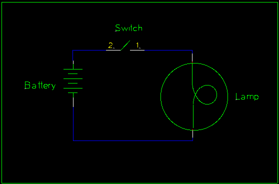
The circuit above shows how to connect a battery, switch, and light. The light can be replaced with the bell or buzzer.
4
There are several low cost motor kits available on the market. Here are links to a few:
It is far more economical to bring in a single motor rather than have each student buy a kit. Small motors can be bought at most hobby stores, and each student can take turns disassembling it.
From Wikipedia, the free encyclopedia:
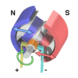
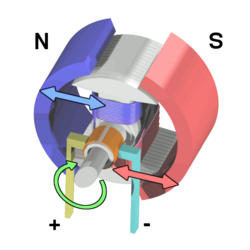
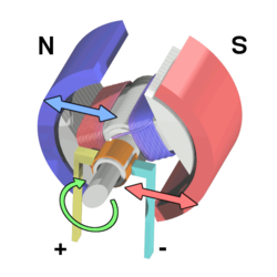
The classic DC motor has a rotating armature in the form of an electromagnet with two poles. A rotary switch called a commutator reverses the direction of the electric current twice every cycle, to flow through the armature so that the poles of the electromagnet push and pull against the permanent magnets on the outside of the motor. As the poles of the armature electromagnet pass the poles of the permanent magnets, the commutator reverses the polarity of the armature electromagnet. During that instant of switching polarity, inertia keeps the classical motor going in the proper direction. (See the diagrams below.)
5
A battery can be made by placing a galvanized (zinc-plated) nail and a copper wire in a small container filled with vinegar. Do not let the zinc and copper terminals touch one another. They can be held apart by punching small holes in the container's lid and inserting them through these holes. A film canister works pretty well for this, but so will a paper or foam cup covered with plastic wrap (or just put the two conductors on opposite sides of the container). As long as the two conductors can both be immersed in the vinegar without touching one another, a voltage should develop between them.
It might help to brighten the nail and the copper with sandpaper or emery cloth first. A cell constructed like this will generate about 0.8 volts. The copper wire will be the positive terminal (anode) and the zinc plated nail will be the negative terminal (cathode).
Connect multiple cells in series to form a battery and boost the voltage. When doing this, be sure to connect the positive terminal (copper) of one cell to the negative terminal (zinc) of the other.
Connect multiple cells in parallel to boost the current capacity (necessary to light up a bulb). To do this, connect all the nails together with one wire and connect all the copper terminals together with another wire.
6
There are many types of fuses. Some of them have threaded bases and can be removed by rotating them counter-clockwise. Others have to be pried out of their holders. Always remember that household current is dangerous, so it is best to cut the power first. This requirement can also be met by changing the fuse in an automobile or appliance (unplug first!).
A breaker is a current-sensing switch. Circuits can be turned off by flipping the switch away from the center of the breaker panel, and turned back on again by flipping the switch towards the center of the breaker panel. When a breaker senses that the current flowing through it exceeds its rated threshold, the switch opens by itself, moving the toggle between the off position and the on position. The breaker is said to have "tripped" when this happens. Before a tripped breaker can be reset, it must first be turned fully to the off position, and then it can be returned to the on position. If the breaker trips again, the circuit is still overloaded. If this is the case, turn off some of the appliances in the circuit before attempting to reset the breaker again.
7
First, do not touch the person! Instead, turn off the power as quickly as possible. If you cannot find the switch, use a non-conducting pole such as a wooden broom handle, a non-metallic chair, a shoe, or some similar object and move the wire off the person. Be sure to move the wire far enough away so that it will not reconnect with the victim when released. Be careful to not touch the wire with any part of your body.
Once the victim has been disconnected from the current, call 911. If the victim is not breathing, start CPR. If the victim is breathing, but unconscious, maneuver the body onto its side to prevent the victim's tongue from blocking the air passage.
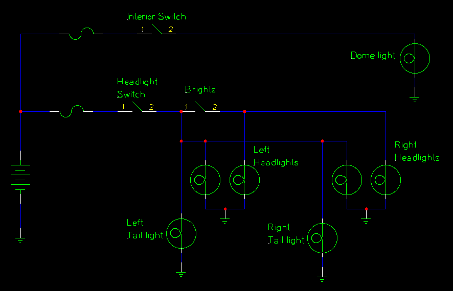
8
9
The schematic above shows a typical circuit in a household. The circuit as shown is protected by a fuse (although a breaker would be applicable as well), and has three loads:
- A light controlled by a single switch
- An unswitched outlet
- A light controlled by two switches
More outlets and switches can be added to the circuit, but note that they will all be connected in parallel. All circuits will connect to the black "'hot'" wire and to the white "'neutral'" wire.
A typical house will have about two dozen breakers, and it is rare for a circuit to have more than about eight outlets or lights. Having too many lights or outlets on a single circuit will cause the breaker to trip or the fuse to blow, so several circuits are run in a house.
10
Electric meters measure electricity in kilowatt hours. One kilowatt hour (kWh) will provide 1000 watts for one hour. Electric companies typically charge a flat rate per kilowatt hour, and this rate can be found on an electric bill. Some electric companies charge varying rates depending on when the electricity is used, charging a lesser rate when electrical demand is lower (such as during the night). For this requirement it is a lot easier to assume a flat rate, but even then utility companies do not always make it easy. For example, they may break the rate down into several components and they may add flat fees as well. If this is the case for you, simply add all the component rates together to get an aggregate rate. The component rates can be very small values - fractions of a penny.
To calculate the rate, one must first read the meter. The meter is not reset when it's read, so one must know what the meter read during the previous billing cycle. The current reading is subtracted from the previous reading, and the difference is multiplied by the rate.
[math]\displaystyle{ bill = \left((current\ reading - previous\ reading)\times aggregate\ rate \right)+flat\ fees }[/math]
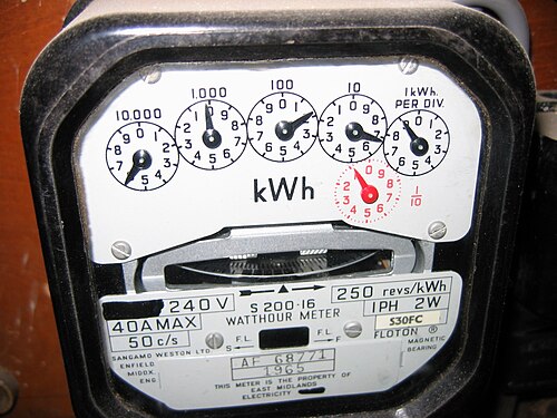
The meter pictured above shows 60169.1 kilowatt hours (not 60279.1 - the dials have not yet reached the 2 or the 7 yet). To calculate an electric bill assume the following:
Previous month's reading: 59023.6 kWh
Aggregate rate: 11.274 cents per kWh
Flat fees: $20
The bill would be calculated as follows:
[math]\displaystyle{ \begin{matrix}bill & =& \left( (60169.1 - 59023.6) \times 0.11274\right) \ +\ $20 \\ \ & =& (1146.5 \times 0.11274)\ +\ $20 \\ \ & =& $129.14\ +\ $20\\ \ &=& $149.14\end{matrix} }[/math]
Note that this is rounded to the nearest cent.
