Difference between revisions of "AY Honors/Radio Electronics/Answer Key"
| Line 124: | Line 124: | ||
=== Simple voltmeter === | === Simple voltmeter === | ||
| + | This link has some material on using an LM3914 as a | ||
| + | [http://www.electronics-tutorials.com/devices/lm3914.htm Bar Graph Meter] | ||
=== Pressure sensor === | === Pressure sensor === | ||
Revision as of 06:34, 6 November 2005
Radio Electronics
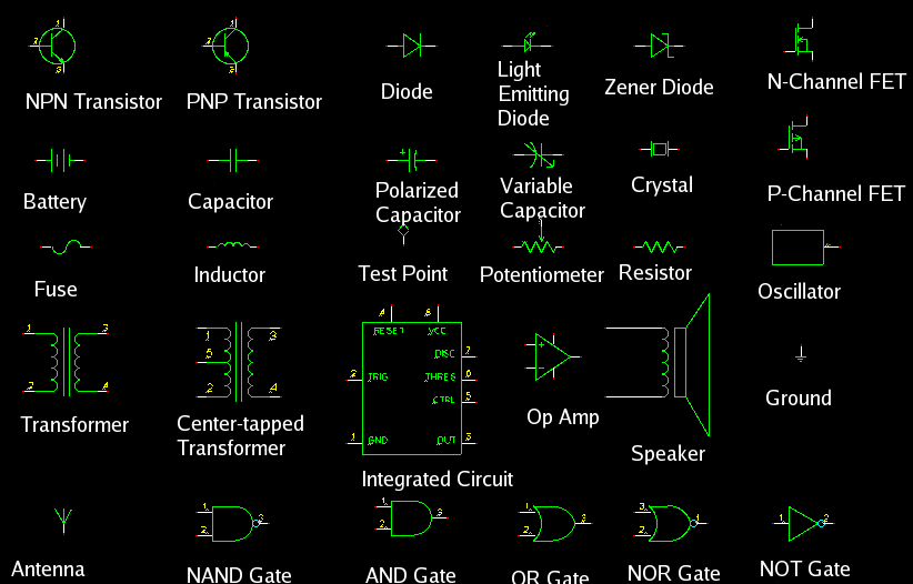
Identify at least 20 symbols used in electronics.
Identify the value of resistors by the color code
The value of a resistor is marked on the device itself by using bands of colors. The color code assigns a number to each of the following colors:
- 0 - black
- 1 - brown
- 2 - red
- 3 - orange
- 4 - yellow
- 5 - green
- 6 - blue
- 7 - violet
- 8 - grey
- 9 - white
Note that after black and brown, the next six colors are arranged as they are found in the rainbow. These colors can also be memorized by the use of a mnemonic such as "Black Bears Run Over Yellow Grass, But Vultures Glide over Water."
Two other colors are used to specify the tolerance of the resistor - that is, how close the actual value is to the value encoded on it:
- 5% - gold
- 10% - silver
If there is no gold or silver band, the resistor has a 20% tolerance.
Remember that just as "gold is better than silver," a 5% (gold) resistor is better than a 10% (silver) resistor.
On a four-band resistor, the third band represents the number of zeros that follow the first two digits, and the fourth band represents the tolerance. So a brown-black-red-gold combination would indicate a 1000 Ohm resistor with a 5% tolerance.
Resistors with tighter tolerance are usually specified with three bands indicating the numeric value and a fourth indicating the number of zeroes following.
Demonstrate proper soldering techniques
Soldering is a way of semi-permanently connecting electronic components together or to a circuit board. It involves heating the solder to its melting point and letting it re-solidify on the components themselves. The heating is done with a soldering iron.
Begin by turning on the soldering iron and waiting until it is hot enought to melt solder. You can test this by touching some solder to the tip of the iron. Clean the tip of the soldering iron by wiping it on a wet sponge. This may be repeated often when soldering a lot of joints.
The connection should also be bright and clean before attempting to solder them. They are often clean enough and require no attention, but if you have difficulty getting the solder to stick, clean them with some solder flux.
Place the tip of the iron on the components you wish to connect and heat them both. Do this while simultaneously touching the solder to the components - do not touch the solder to the iron. The goal is to heat the components to the point where they are able to melt the solder themselves. Otherwise you will end up with a "cold" solder joint which will fail sometime in the future.
If soldering wires, twist them together first. Although solder has a small amount of mechanical strength, it is not sufficient to withstand very much stress. Therefore, it should not be relied upon for anything other than making an electrical connection. If the joint is stressed, it can easily fail.
And always remember - solder is HOT, as are freshly soldered electronic components.
Explain the use and operation of various important components in electronics such as resistors, variable capacitors, fixed capacitors, coils, transistors, integrated circuits, diodes, and transformers.
Resistor
The function of a resistor is to limit the current in a circuit. Resistors can also be combined into "voltage divider" circuits by placing them in series.
Fixed Capacitor
A fixed capacitor can be used to hold a charge. They are often used to smooth noise out of power supply circuits by placing them in parallel with the power supply. A capacitor cannot pass DC if it is placed in series. This is because the impedence of a capacitor varies with the frequency, and at zero Hertz (DC), its impedence is infinite. Large capacitors have less impendence at a given frequency than a small capacitor, and because of this, capacitors can be used in "frequency selective circuits" such as filters.
Variable Capacitor
A variable capacitor can be used in a frequency selective circuit where the user has control over the selected frequency. An example of this would be in a radio or television tuner.
Coil
A coil is also known as an inductor. The impedence through a coil is also frequency dependent, but in the opposite way as in a capacitor. At DC, an inductor has nearly zero impedence, and the impedence increases with higer frequencies. Inductors are often used in conjunction with capacitors in frequency selective applications. They are also often used for filtering out noise from power supplies. Since a power supply is supposed to provide a constant voltage (0 Hertz), an inductor can be placed in series between the supply and the load. The inductor will absorb the higher frequencies so that the load does not see them.
Transistor
A transistor has two basic applications - it can be used as a switch and it can be used as an amplifier. The current from the collector is proportional to the current flowing from the base to the emitter. If no current flow from the base to the emitter, no current can flow from the collector to the emitter. In this regard, the transistor acts as a switch. A small signal can be amplified by injecting it into the base of the transistor. In this case, the current from the collector to the emitter is amplified.
Integrated Circuit
An integrated circuit - or "chip" is a collection of transistors and resistors etched into a silicon (or other semiconducting material) chip. Very complicated circuits can be built by combining many transistors onto a single chip. The number of transistors that can be put on a single chip is well over a million.
Diode
A diode is a device that allows current to flow in one direction, but not in the other. This can be used in constructing an AC to DC converter, or for protecting a circuit from outside voltage sources.
Transformer
A transformer consists of one or more coils located within close proximity to one another. When current passes through a coil, it generates a magnetic field. When the current varies, so does the magnetic field. When a varying magenetic field is set up near a coil, a current is induced in that coil. By placing two coils in a common magnetic field and injecting a varying current into one (the primary), a proportional current is induced in the other (the secondary). The ratio depends on how many turns each coil has. If a transformer boosts the voltage, it will reduce the current, and if it reduces the voltage, it will increase the current. Thus, the power through the transformer is preserved (other than a loss). Electric companies transmit power by passing the electricity through step up transformers so that less current (but very high voltage) can be transmitted over long distances. This decreases power loss through the transmission lines which have fixed resistance. The voltage is stepped down again before it is delivered to a customer.
Transformers are also used to isolate two circuits so that only AC passes between them and their DC power supplies do not interfere with one another.
Know and understand Ohm's Law.
If a voltage is applied across a resistor, current will flow through it. Ohm's law describes the relationship between this current, voltage, and resistance. It can be written as
[math]\displaystyle{ v = i r }[/math]
Where v is volatage (measured in volts), i is current (measured in amps), and r is resistance (measured in ohms). The equation can also be written as
[math]\displaystyle{ i = \frac{v}{r} }[/math]
and
[math]\displaystyle{ r = \frac{v}{i} }[/math]
Basically, it means that if the voltage is held constant and the resistance is decreased, the current is increased. Or if the resistance is held constant and the current is increased, the voltage will also increase.
Determine how to correctly place or pin integrated circuits, transistors, diodes, and capacitors in a circuit board.
Integrated Circuits
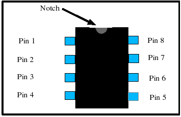
Integrated circuits usually have some means of indicating where "pin 1" is on the device. Once pin 1 is located, the remaining pins are numbered going counter-clockwise around the device. On a DIP, pin one is located to the left of a notch milled into the top of the IC as shown below:
Transistors
Diodes
Capacitors
What is meant by a parallel and a series circuit?
A series circuit is a circuit in which the components are placed end-to-end. The circuit below shows two resistors in series:
o---/\/\/\-----/\/\/\----o
In a series circuit the current flowing through both devices will be equal, but the voltage across them will be different if the resistances are different.
A parallel circuit connects both terminals of two components together. The circuit below shows two resistors in parallel:
     +----/\/\/\----+
o----+              +------o
     +----/\/\/\----+
In a parallel circuit, the voltage across the two resistors will be identical, but the current divides between them. Some current goes through the top, the rest goes through the bottom.
From a kit or from scratch make two of the following:
Photocell Guard or Counter
The Photocell Guard circuit is a photo sensitive switch that will either turn on or turn off some device. In modern terminology, it would be called a photo-sensitive switch. A Photocell Counter is a circuit which counts the number of times a photo-sensitive switch is activated. In modern terminology, it would be called a Photo-sensitive Counting Circuit.
Siren
Simple voltmeter
This link has some material on using an LM3914 as a Bar Graph Meter
Pressure sensor
Simple DC power supply
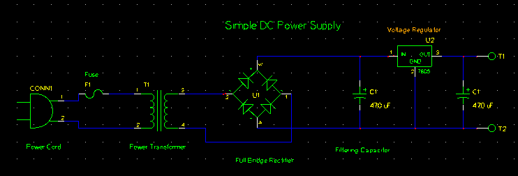
In this DC power supply, household current (120VAC, 60Hz in North America) is applied to the power cord on the left. The fuse protects the circuit and should not be omitted. The voltage is then stepped down by the power transformer. These are available at Radio Shack, and at hardware stores (see the doorbell section). Try to select a transformer that will output a voltage close to the but a little higher than the desired DC output voltage.
Once the voltage has been stepped down, it goes through a network of diodes set up as a "full bridge rectifier." The diodes direct current to the top of the network and allow it to return through the bottom, regardless of whether the input voltage is positive or negative.
The capacitor then smoothes out the voltage. Without the capactitor, the output from the diode network would continually drop to zero, and then rise ack up to its peak value. The capacitor averages this out.
The next element in the circuit is the power resistor and the zener diode. A zener diode, when reverse biased, will clamp the voltage to a constant value. This value depends on the zener diode selected. The "extra" voltage is dropped across the power resistor. This resistor must be carefully selected. It must be capable of dissipating several watts of power, and it needs to have a low value. The lower the value, the more current the circuit can supply to the load - but at the same time, the more power it will dissipate. Values for the fuse and the resistor should be chosen together, such that the fuse will prevent the resistor from dissipating more power than its rating allows. It will get very hot, and could catch on fire if over burdened. The power the resistor will need to dissipate will depend on its resistance, and on the difference between the zener's voltage and the transformer's output voltage:
[math]\displaystyle{ P = \frac{(V_t - V_z)^2}{R} }[/math]
Where [math]\displaystyle{ P }[/math] is the power dissipated by the resistor, [math]\displaystyle{ V_t }[/math] is the voltage output by the transformer, [math]\displaystyle{ V_z }[/math] is the zener's voltage, and [math]\displaystyle{ R }[/math] is the resistance.
The resistor/zener diode combination can also be replaced with a linear voltage regulator such as an LM7805 (5 volts) or an LM7812 (12 volts). This will likely yeild more satisfactory results.
Since the zener diode will hold the voltage to a constant value, the DC power supply's output can be taken in parallel - in the circuit diagram it is applied to the two terminals. The terminal on the top will be the positive voltage, and the terminal on the bottom will be ground.
All the parts in this circuit can be purchased at Radio Shack, or over the Internet from suppliers such as Digikey or Jameco.
The circuit should be mounted in some sort of enclosure to protect the 120VAC input power terminals.
Simple transistor radio
Draw from memory, using proper symbols, the complete wiring diagram of the devices constructed in requirement 8.
List ten ways electronics are used in everyday life.
- Computers - for work and for play.
- Entertainment - Televisions, stereos, video games, toys, etc.
- Medical - Patient monitoring, diagnostics (MRI, CT-scans, X-rays), etc
- Industrial - motor controllers, robotics, etc.
- Appliances - microwaves, timers, ovens, refrigerators, washing machines, dryers.
- Radio Communications - police and fire radios, CB radios, fleet radios.
- Telecommunications - telephones, fax machines.
- Fire Safety - fire alarms, smoke detectors, sprinkler systems.
- Water Supply - water towers signal pumping stations, etc.
- Security - metal detectors and x-ray machines at airports, anti-theft devices in stores, security camera.
- Music - amplifiers, synthesizers, sound mixers, recording equipment.
- Traffic Control - traffic signals.
- Automotive - Air bags, antilock brakes, diagnostics, electronic ignition, etc.


